Illuminauta

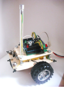
Complete Carduino Build Guide

Step-by-Step Instructions to Build Your Own Arduino-Based Mini Robot

Carduino Front View
Carduino Side View

Operating Modes

Understanding Carduino's three modes of operation

🎮

Remote Control Mode

Control Carduino via Processing interface with real-time direction and speed commands from PC.

Bluetooth communication
Real-time control
User interface
Speed and direction control
🚫

Obstacle Detection Mode

Autonomous movement at constant speed, modifying trajectory to avoid obstacles.

Autonomous operation
Obstacle detection
Path correction
Continuous movement
🔊

Sound Navigation Mode

Autonomous movement that changes trajectory when detecting loud sounds.

Sound detection
Autonomous navigation
Direction changes
Environmental response

Required Components

Complete parts list for building Carduino

Main Platform

Arduino BT Platform (Arduino)
x1
Proto-shield (Shield)
x1
Micro pushbutton 12x12 (Reset)
x1
Resistors (Rs1,Rs2)
x2
LEDs (Green/Red) (Ls1,Ls2)
x2

Power System

Rechargeable AA Batteries 1.2V NIMH 1500MAH (Baterías)
x6
Battery holder for 6 batteries (Portapilas)
x1
Charger (Cargador)
x1
7805 Regulator (Rp1)
x1
Capacitor 1nF (Cp1,Cp2)
x2
Capacitor 100uF (Cp3)
x1
Capacitor 22uF (Cp4)
x1
100uH Coil (Lp1)
x1

Motor Control

H-Bridge L293D (Control de motores)
x1
DC Motor Reducer 50:1 (M1,M2)
x2

Sensors

Infrared Sensor CNY70 (Inf1,Inf2)
x2
Long neck pushbutton (P1-P6)
x6
3-pin electret microphone (Mic)
x1
Resistor 2.7kOhms (Rd0,Rd3)
x2
Resistor 10kOhms (Rd1)
x1
Resistor 3.9kOhms (Rd2)
x1
Resistor 1.2kOhms (Rd4)
x1
Resistor 510Ohms (Rd5)
x1

Odometers

Resistor 220 Ohms (Ro1)
x2
Resistor 10kOhms (Ro2)
x2
White cardboard (Cartulina)
x1

Mechanical Parts

Traction wheels (RuedaIzq,RuedaDer)
x2
Metal-plastic free wheel with nut (RL)
x1
Spacer screws without tip (Tornillos)
x4
Nuts for screws (Tuercas)
x12
Marquetry panel for bases (Panel de chapó)
x1
Perforated bakelite board (Pcb)
x1

Cables & Connectors

Wire 0.28mm (5 colors) (Hilo)
x5m
Male pin strip (Pines macho)
x1
Female pin strip (Pines hembra)
x1
Single female pin strip (Pines Hembra)
x2
Round aerial connector 2-way large (ConM1)
x1

Accessories

Insulating tape (Cinta aislante)
x1
Teflon tape (Cinta Teflón)
x1
Cable ties (Brida)
x1
Solder (Estaño)
x1
Contact adhesive (Adhesivo de contacto)
x1
Bic pen (Bic)
x1

Required Tools

PC

For software loading

USB Cable

Connection between mini-robot and PC

Wire Stripper

Cutting and stripping cables

Punch

For making perforations

Sandpaper

Sanding marquetry panel, rounding edges

Cutter

Cutting marquetry panel and bakelite board

Soldering Iron

For making electronic component connections

Desoldering Pump

For removing poorly made connections

Required Software

🤖

Arduino IDE

1.8.x or newer

Integrated Development Environment for Arduino programming

Code editing and compilation
Sketch upload to Arduino board
Serial monitor for debugging
Library management

Processing IDE

3.5.x or newer

Development environment for the Processing programming language

User interface development
Real-time robot control
Visual programming environment
Cross-platform compatibility
📚

Firmata Library

Included with Arduino IDE

Standard protocol for communicating with microcontrollers

PC to Arduino communication
StandardFirmata sketch included
Real-time control capabilities
Cross-platform support
🔗

Bluetooth Drivers

System dependent

Drivers for Arduino Bluetooth module communication

Bluetooth module recognition
Serial communication setup
Device pairing support
115200 baud rate configuration

Educational Documents

📖

Arduino Basics

Comprehensive guide to Arduino basics, terminology, and programming fundamentals

📖

Arduino Libraries

Step-by-step guide to creating custom Arduino libraries with practical examples

📖

Circuit Simulation

Complete guide to electronic circuit simulation using Proteus software

📖

PC Communication

Guide to establishing communication between PC and Arduino for data exchange

📖

Soldering Guide

Essential tips and techniques for achieving quality soldering in electronics projects

Step-by-Step Assembly

Complete construction guide with detailed instructions

1

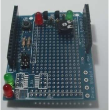
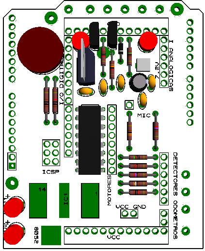
Basic Shield Assembly (v4)

Solder male pin strip to shield inputs/outputs, add resistors [Rs1,Rs2], reset button, and LEDs [Ls1,Ls2]. Add female-female connectors for stacking shields.

Solder straight male pin strip to shield inputs and outputs
Add resistors Rs1 and Rs2
Install reset button
Add status LEDs Ls1 (green) and Ls2 (red)
Add female-female connectors for shield stacking capability
2

Power System Assembly

Assemble power cable and power stage components for battery management.

Create power cable with round aerial connector and male pins
Mount round aerial connector on one end
Add two straight male pins on other end and bend to final position
Cover one pin with insulating tape to prevent shorts
Install voltage regulator 7805
Add filter capacitors Cp1, Cp2
Add power capacitors Cp3, Cp4
Install power coil Lp1
Connect power stage to power cable
Ensure correct battery polarity (+ and - terminals)
Step 2 - Image 1
Step 2 - Image 2
Step 2 - Image 3
3

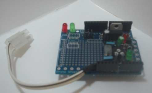
Status LEDs Installation

Install status LEDs near front of shield for easy battery state visualization.

Position LEDs as close as possible to shield front
Connect to power stage
Ensure proper orientation (anode/cathode)
Test LED functionality
4

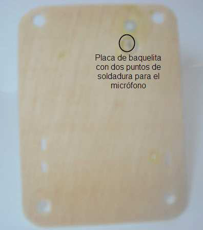
Platform Preparation

Download templates and prepare platform structure with perforations and bakelite boards.

Download platform templates (click image below to download)
Make all indicated perforations according to templates
Cut bakelite board sections according to templates
Fix bakelite sections to platforms
Prepare upper and lower platforms
Step 4 - Image 2
Step 4 - Image 3
Step 4 - Image 4
Step 4 - Image 5
Step 4 - Image 6
5

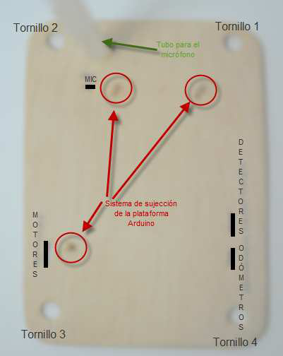
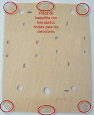
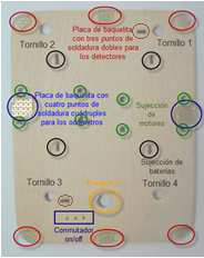
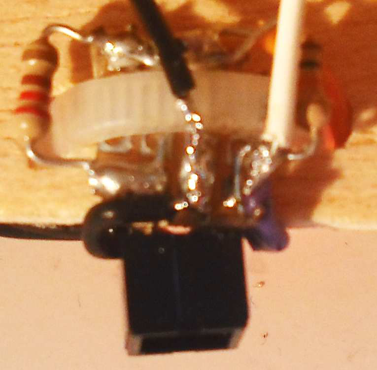
Obstacle Detectors Installation

Mount pushbutton sensors on bakelite boards with proper wiring.
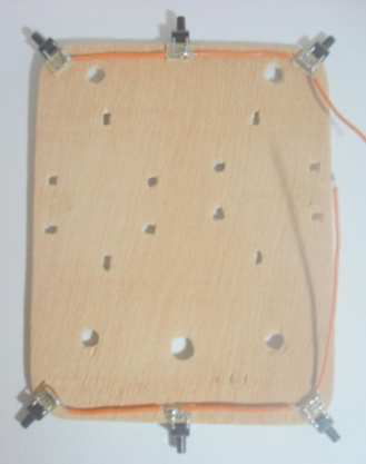
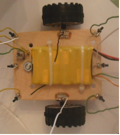
Fix pushbuttons to bakelite boards
Connect right leg to 5V on bottom
Connect right terminal (opposite diagonal) to shield input
Ensure proper contact and insulation
Test all 6 detectors
6

Motor Installation

Fix two motors [M1, M2] using cable ties through created perforations.

Use created perforations for motor mounting
Fix motors with cable ties
Ensure motors are securely mounted
Position motors before odometer installation
Prepare for odometer components
7

Odometers Assembly

Install infrared sensors for odometry with proper resistance connections.

Fix odometers as close to platform as possible
Connect each odometer leg to a resistor
Connect resistor terminals to 5V
Connect both odometer legs to ground
Output to shield between receiver and 10k resistor [Ro2]
Use motor cable tie perforation for 5V connection
Step 7 odometer assembly
8

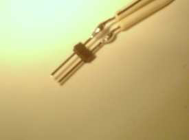
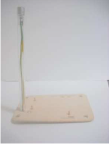
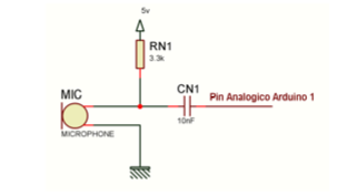
Microphone Installation

Mount 3-pin electret microphone with proper wiring and insulation.

Cut two cables longer than tube length
Solder microphone terminals
Protect terminals with insulating tape
Pass cables through tube
Solder to bakelite board behind upper platform
Connect ground terminal to ground
Connect remaining terminal to shield input
Step undefined - Image 1
Step undefined - Image 2
9

On/Off Switch Installation

Install power switch with proper terminal connections.

Center cable is output
Left cable is ground
Right cable is 7.2V input from shield
Ensure proper insulation and mounting
Step undefined - Image 1
Step undefined - Image 2
10

Battery Installation

Mount battery holder to ensure proper cable lengths for shield connection.

Install 6-battery holder
Ensure proper cable lengths
Connect to power system
Test battery connections
11

Wiring Assembly

Complete all wiring connections following detailed schematics.

Connect all ground points together (black cable)
Connect all Vcc points together (orange cable)
Connect odometer grounds
Connect switch ground
Connect microphone ground
Connect all pushbutton left legs to Vcc
Connect motor cables (white and green)
Connect odometer outputs (white and black)
Pass all cables through platform perforations
Step undefined - Image 1
Step undefined - Image 2
12

Separation Screws

Install separation screws with proper nut positioning.

Insert nuts from upper to lower platform
Use first lock nut to secure upper platform position
Use remaining two nuts to fix lower platform position
Ensure no excess nuts below last nut
13

Connector Installation

Add connectors to cable terminals and mark for easy identification.

Add connectors to all cable terminals
Mark shield connectors and cable connectors
Ensure proper connection identification
Test all connections
14

Shield Assembly

Mount shield according to circuit map and wiring connections.

Follow circuit map from chapter 4
Follow connections from chapter 6
Position resistors to save space
Interconnect all ground points
Interconnect all Vcc (5V) and 7.2V points
Use socket or female pin strip for IC
Test connections with multimeter after each layer
Step undefined - Image 1
Step undefined - Image 2
15

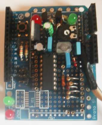
Arduino Platform Integration

Attach shield to Arduino platform and position on upper platform.

Attach shield to Arduino platform
Position on upper platform
Make connections through connectors
Ensure proper alignment and mounting
16

Counterweights

Add counterweights for proper balance and stability.

Create lead piece or use metal balls
Cover with Teflon tape to prevent contact
Position for proper balance
Test robot stability

Wiring Diagrams

Detailed connection schematics for all components
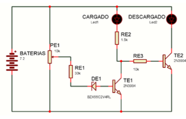
Status LEDs

Connection diagram for status LEDs showing proper resistor values and connections.

Status LEDs wiring diagram
LEDs Ls1, Ls2
Resistors Re1, Re2, Re3
Transistors Te1, Te2
Zener diode De1

Power Stage

Complete power stage wiring including voltage regulator, capacitors, and power coil.
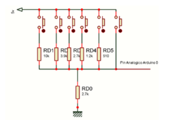
Power Stage wiring diagram
7805 Regulator
Capacitors Cp1-Cp4
Coil Lp1
Power connector

Obstacle Detectors

Wiring for all 6 pushbutton obstacle detectors with proper resistance values.

Obstacle Detectors wiring diagram
Pushbuttons P1-P6
Resistors Rd0-Rd5
Voltage dividers

Sound Navigation

Microphone circuit with amplification and filtering components.
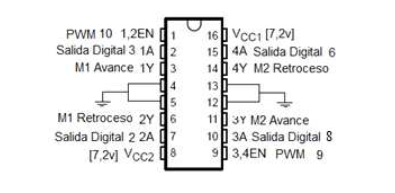
Sound Navigation wiring diagram
Electret microphone
Resistor Rn1
Capacitor Cn1

Motor Control

H-bridge L293D motor driver connections for both motors.

Motor Control wiring diagram
L293D H-bridge
Motors M1, M2
Control signals

Odometers

Infrared sensor CNY70 connections for wheel rotation sensing.

Odometers wiring diagram
CNY70 sensors Inf1, Inf2
Resistors Ro1, Ro2
Voltage dividers

Software Implementation

Arduino code and Processing interface setup

📦

Complete Source Code

Download the complete Carduino project with all Arduino sketches and libraries

Obstacle Detection

1
Connect USB cable to Arduino platform
2
Open Arduino IDE
3
Verify correct port and Arduino model
4
Upload Detectores.pde sketch
5
Disconnect PC from Arduino
6
Connect batteries
7
Position robot on ground
8
Turn On/Off switch to On position

Sound Navigation

1
Connect USB cable to Arduino platform
2
Open Arduino IDE
3
Verify correct port and Arduino model
4
Upload Navegacion.pde sketch
5
Disconnect PC from Arduino
6
Connect batteries
7
Position robot on ground
8
Turn On/Off switch to On position

Remote Control

1
Connect USB cable to Arduino platform
2
Open Arduino IDE and Processing IDE
3
Verify correct port and Arduino model
4
Upload Dirigible.pde sketch
5
Disconnect PC from Arduino
6
Connect batteries
7
Position robot on ground
8
Turn On/Off switch to On position
9
Run Processing interface for control

⚠️ Important Safety Notes

Always disconnect battery cable and keep On/Off switch in Off position when connecting USB cable to PC.
Test all connections with multimeter after each assembly layer to catch errors early.
For Arduino Bluetooth version: Use 115200 baud rate, pair but don't connect with PC Bluetooth module.
Pin 7 on Arduino BT is reserved for reset only - implement in upper shield for better access.

Conclusion

Carduino demonstrates the potential of embedded systems in creating intelligent, connected devices for modern living. This project serves as an excellent foundation for learning robotics, electronics, and programming while providing a practical platform for artistic and educational applications.

© 2025 Illuminauta. Crafted with ❤️ and lots of ☕